Get a vertical turbine apart so it can go back together
Turbines don't come with an O&M or shoulders that only fit one way. Whatever you record at intake is all anyone has to rebuild it, sometimes months later. This walks through the forms, the parts, the tools, the three measurements you can't skip, and the math behind the numbers on the form.
Put the right form on the job first
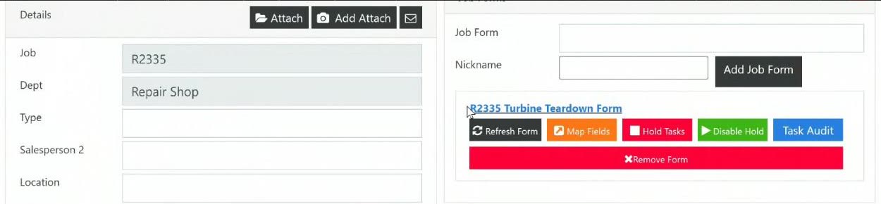
You don't have to wait on inside sales. Once a job has a number, you can add the form yourself.
- Get the job number from inside sales.
- In QM Wizard, open QM Dash → Jobs without forms and search the job number.
- Add the Turbine Teardown Form for a vertical turbine, or the Horizontal Teardown Form for a horizontal/centrifugal pump.
- Adding a second form of the same type? Type something in Nickname (like "2"). Without a nickname it won't save.
- Open the form from Quality Manager by job number.
Fill in the header
Job number, sales rep, date and contact info come from sales (contact info is often blank, and that's fine). The one to chase: why the pump came in. Ask the salesperson or inside sales so you know what to look for during teardown. Note any rush or requested lead time too.

In the recording: job forms from about 0:36.
Three main sections, plus the motor
Tap each section of the pump. Green outlines show the ones you've looked at.
Which way do the threads go?
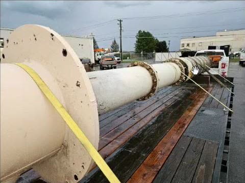
In the recording: pump sections from about 14:55, threads 17:27.
Only two special tools
Most of a turbine comes apart with pry bars, pipe wrenches, regular wrenches and sockets. The two you won't find in a normal shop:
How a collet comes off
A collet is a split, tapered wedge driven between the shaft and the impeller hub to lock the impeller in place.
- Clean the shaft so the knocker can slide along it. Leave the crud on and it'll bind.
- Strike the impeller's hub face evenly all the way around with the collet knocker, driving the impeller backward off the collet.
- You'll know it broke loose: a high-pitched ring, or the impeller spins on the shaft.
- Wedge a screwdriver in the collet's slit to open it and slide it off.
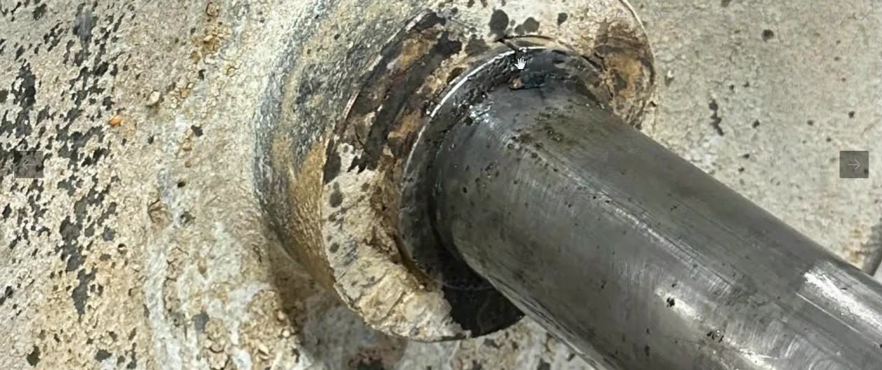
In the recording: tools from about 5:36, collets 11:15, chain wrenches 54:29.
Three measurements before anything comes apart
1Overall length (OAL)First thing, as soon as it shows up. Takes seconds.Easy, don't skip
Measure from the base of the discharge head, where the pump sits, to the lowest point of the pump: the bowl assembly plus column pipe.
Why: many turbines sit in cans of fixed depth. If a new bowl assembly or column comes back a few inches longer, it won't fit. It's happened: a customer added a strainer that stuck out a couple of inches, and the pump wouldn't sit down in the can.
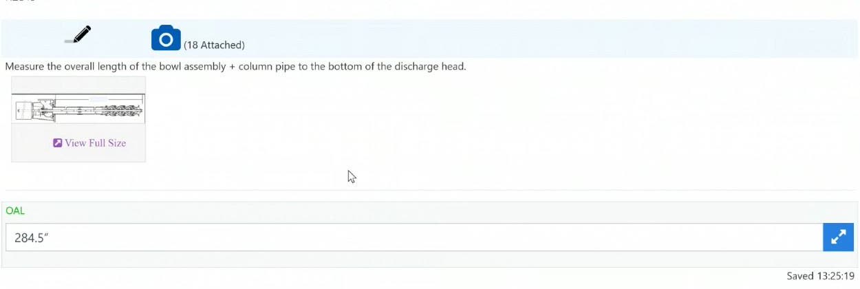
2Dimension D (shaft stick-up)Top of shaft to the motor mounting surface.2nd worst to miss
- Push the shaft all the way down.
- Lay a straight edge across the motor mounting face of the head.
- Tape-measure from the end of the shaft (seen through the head window) up to the straight edge.
- The head has a register, a raised centering ring (often about ⅛″). The motor doesn't sit on it; it sits on the machined surface outside it. If your straight edge rests on the register, subtract the register thickness.
Why: it's what a manufacturer asks for to build a head that fits the existing motor. On a hollow-shaft motor, being off by about ¼″ is usually OK. Much more and you'll have problems.
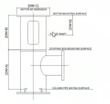
3Build tool depthThrough the plug at the bottom of the suction case.Worst to miss
Miss this and the pump can't be rebuilt. If you forget it at intake, you can still get it any time before the last impeller comes off.
- Remove the grease plug at the very bottom of the suction case (lefty-loosey). Expect grease and water.
- Push the shaft all the way down. Tap the top end with a rubber mallet, not a metal one. Listen for metal-on-metal, or look up into the suction case to check there's no gap under the impeller.
- Using the depth rod on the end of your calipers (not the jaws), measure from the flat end of the shaft to the edge of the suction case. Measure the flat, not the center hole or dimple.
- Use calipers, not a tape. This one needs to be exact (example: 3.755″).
Why it matters: on a colleted pump an impeller can lock anywhere on the shaft. During assembly the build tool holds the shaft at this exact position so every impeller seats fully in its bowl and wear ring. Without it, the shaft creeps up and each impeller ends up a little higher, eventually riding out of its wear surface. Keyed-and-collar impellers sit in machined grooves, so the build tool doesn't apply to them.
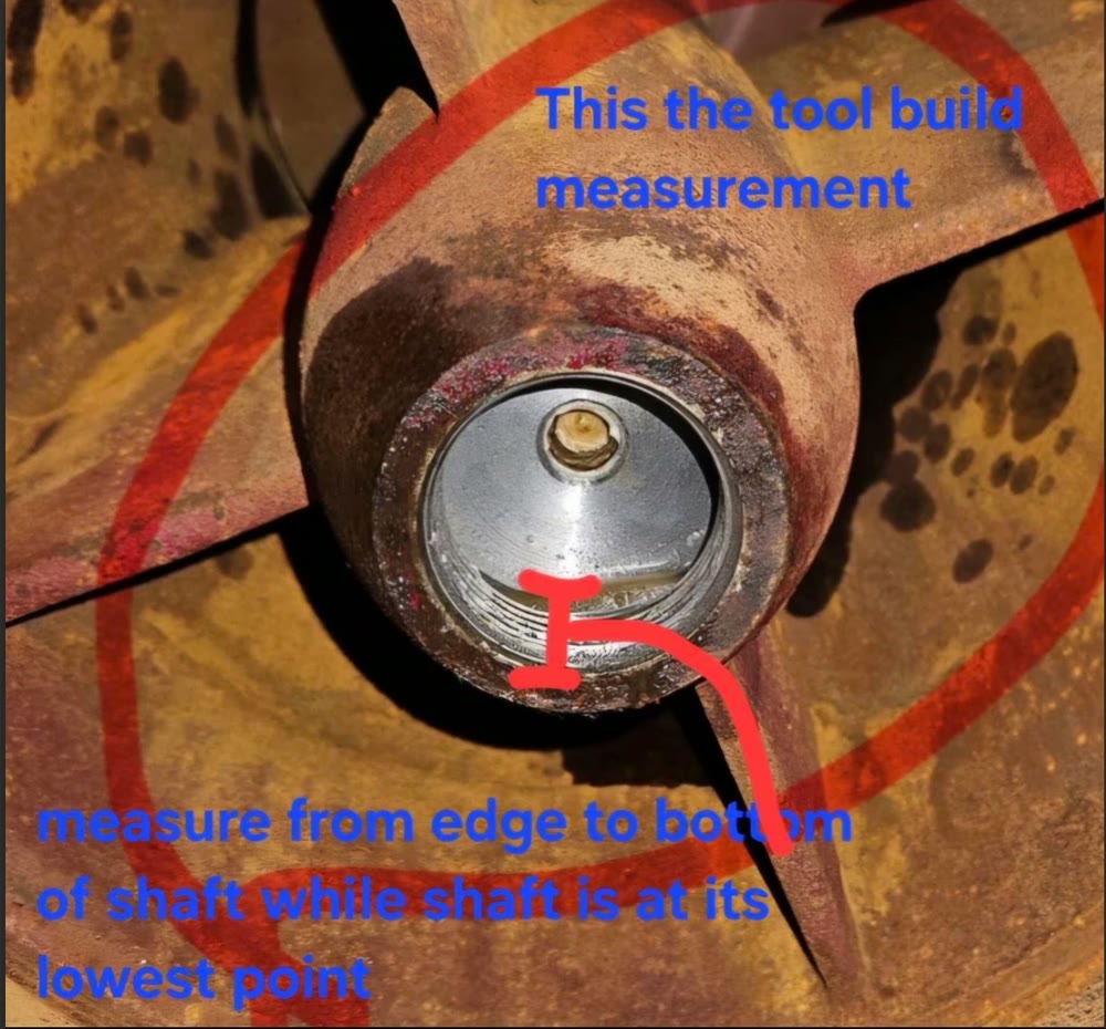
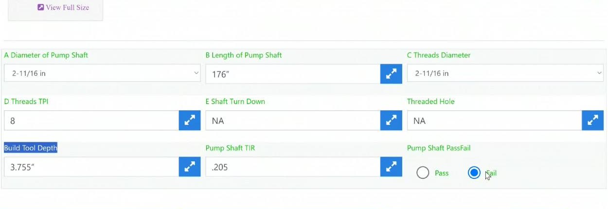
In the recording: overall length from about 18:47, Dimension D 26:54, build tool 39:32 and 40:39.
Conversions and calculations on the form
The form mixes fractions (2-15/16 in) and decimals (3.755″), and several checks are subtraction against a limit. Try each calculator with real numbers.
Fraction ↔ decimal
Type a fraction like 2-15/16 or 3/8, or a decimal like 2.6875.
Bearing clearance
Clearance = bushing ID − shaft OD. Rhino's rule of thumb: up to about double the original clearance (e.g. 0.008″ new → ~0.016″ max).
Shaft TIR
On V-blocks with dial indicators, spin slowly and read the total swing. Industry spec is about 0.002″ over 10 ft (~0.001″ per side). Rhino allows up to 0.002″ per side.
Dimension D
If the straight edge sat on the register, subtract its thickness to get the measurement to the machined surface the motor sits on.
| 1/16 | 0.0625 | 1/8 | 0.125 | 3/16 | 0.1875 | 1/4 | 0.25 |
| 5/16 | 0.3125 | 3/8 | 0.375 | 7/16 | 0.4375 | 1/2 | 0.5 |
| 9/16 | 0.5625 | 5/8 | 0.625 | 11/16 | 0.6875 | 3/4 | 0.75 |
| 13/16 | 0.8125 | 7/8 | 0.875 | 15/16 | 0.9375 | 1 thou | 0.001 |
Other numbers on the form
- Stages = the number of impellers. Count them as they come off, because some bowls have none.
- Pump size = the bowl diameter, measured once the bowls are off.
- Nameplate (TDH, gpm, rpm, manufacturer): fill in what's there. Eight times out of ten it's missing or incomplete on old turbines, and that's OK. It only matters if a whole new bowl assembly is being bought.
- Motor: megger (insulation) test, and note VHS (hollow shaft, shaft runs through the motor) or VSS (solid shaft, coupled underneath).
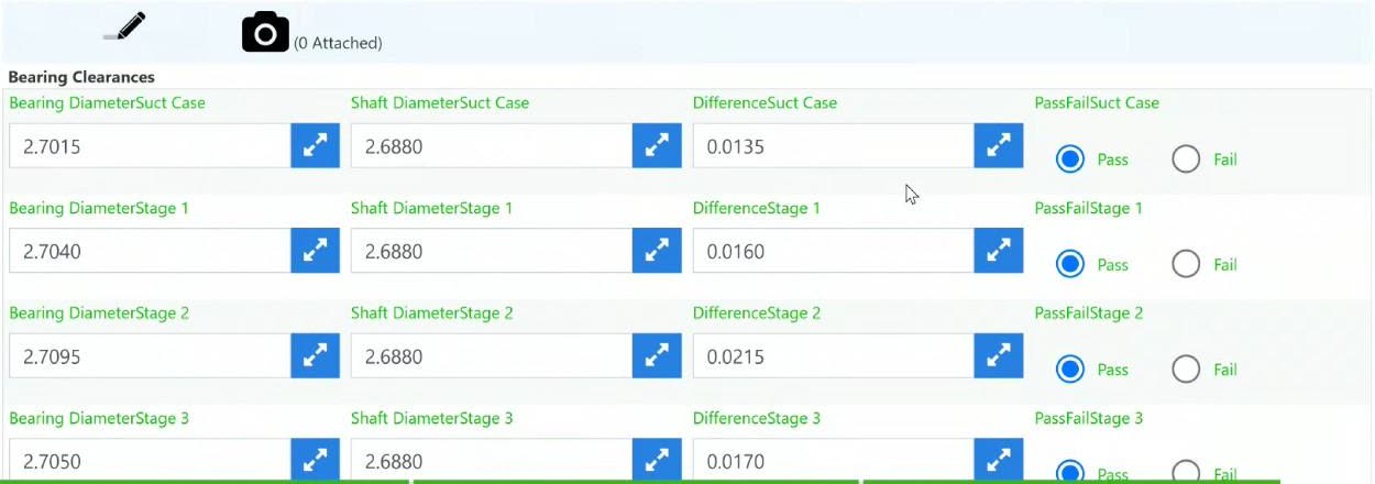
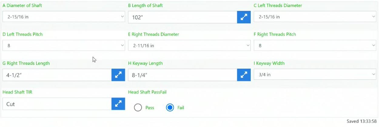
In the recording: nameplate from about 20:01, motor 23:22, TIR 24:53, bearing clearances 37:48.
Document it like nobody will remember it, because they won't
Horizontal pumps have shoulders and O&M diagrams, so parts mostly only fit one way. Turbines don't. And city jobs can sit for months waiting on parts.
- Photos at every transition, not just "assembled" and "pile of bolts". Each stage of coming apart should be in the photos, so whoever picks it up in a month can follow it.
- Mark the outside parts (column pipe, bowls) so they go back in the same orientation. Keep shafts in the order they came off.
- Only enter numbers you're sure of. Fill in what you can, then have Utah look it over and give the OK before disassembly.
- Can't see the bolt heads? It may need sandblasting first. The local shop behind the Idaho yard can blast and coat parts up to about 30–40 ft long, usually in a day or two. Send their price list to Jared for approval.
- Submersible or drinking-water parts need NSF-rated coatings that won't contaminate the water. Check the shop knows the spec; Jared can provide it.
What always gets replaced
Write these down on every turbine, even if they look good: shafting (it gets bent, pitted and chewed by chain wrenches during teardown, so you don't need to baby it), collets, couplings, and the mechanical seal or packing. The rare exception is a very large, expensive shaft, like a 5″ one that was cleaned up and reused.
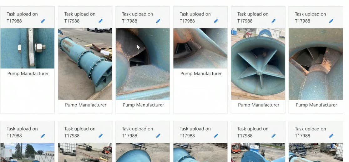
In the recording: marking parts from about 33:17, replaced parts 50:03, sandblasting and coatings 59:03, photos 1:04:37.
A turbine just came in. What happens first?
Tap the steps in the order you'd do them.
Ten questions to finish
Score 8 or more to pass.
Watch the full session recording69 minutes · the October 5 intake call this training is based on
Built from the session recording, its meeting notes and screenshots of the QM Wizard teardown forms. When something on a pump doesn't match, ask Utah before you guess.